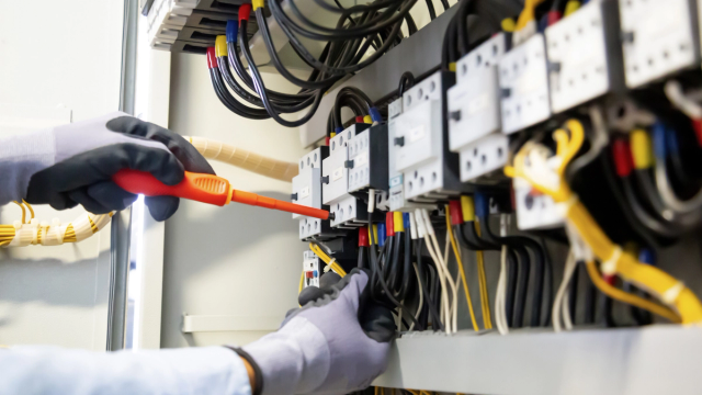
Electrical & Energy Systems
Electrical installation, maintenance, fault diagnosis and solar energy solutions for residential, commercial and industrial environments. We work across the systems that distribute, use and supply electrical power.
Case study
An automated pump-control prototype developed to manage water-pumping cycles while monitoring operating conditions and responding to faults.
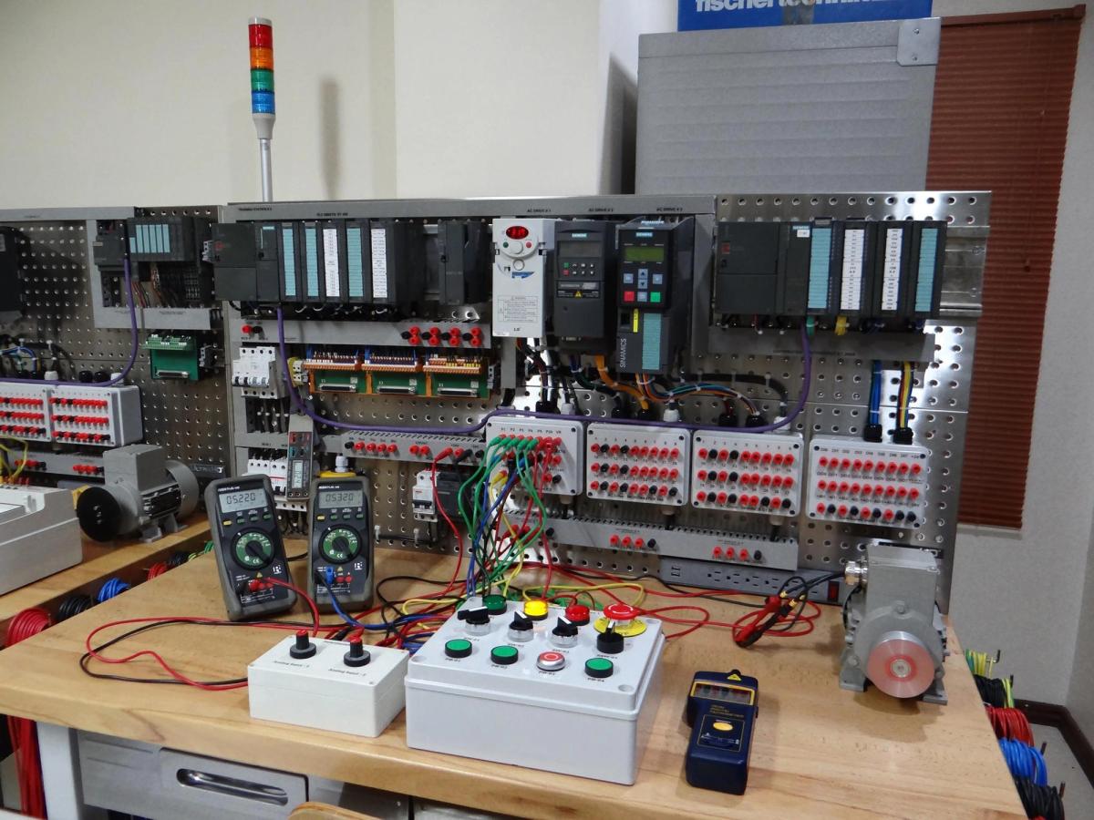
A basic pump-control arrangement can switch a motor on and off in response to a level switch or manual command. However, reliable operation involves more than deciding when a pump should run. Dry running, overload conditions, conflicting sensor signals, and repeated starting can all interfere with operation or place unnecessary stress on equipment.
This project developed a pump-control system that treated these conditions as part of the control problem rather than as separate issues to be handled after a failure.
The prototype used a programmable logic controller to manage the operating sequence. Level switches provided the signals required to determine when pumping should begin and when the target level had been reached. A motor contactor switched the pump, while an overload relay provided a separate protective mechanism. Additional inputs represented conditions such as low source-water level and abnormal operating states.
The control program was organized around explicit operating states, including stopped, ready, running, and faulted. Before starting the pump, the controller checked that the required permissive conditions were satisfied. During operation, it continued monitoring the relevant inputs. A detected fault interrupted the normal sequence and activated a fault indication rather than allowing the system to continue operating as though conditions were normal.
The design also included a manual operating mode for controlled testing and maintenance. Manual operation did not bypass the motor's electrical protection. Fault conditions requiring inspection had to be acknowledged and cleared before the system could return to automatic operation.
The prototype was tested using simulated sensor inputs and controlled fault conditions. These tests examined normal start and stop sequences, low-source-water conditions, overload trips, sensor conflicts, and recovery after a fault. The testing process helped expose edge cases that would be easy to overlook in a simple relay-based sequence, particularly when sensor signals changed unexpectedly or a fault occurred during a pumping cycle.
The completed control system demonstrated how a small PLC-based installation could combine automatic operation with explicit fault handling and clearer operator feedback.
THE END
Electrical installation, maintenance, fault diagnosis and solar energy solutions for residential, commercial and industrial environments. We work across the systems that distribute, use and supply electrical power.

Industrial control, PLC programming, control panel development and automation integration for processes and equipment. We work towards making operations more consistent, observable and manageable.
Describe the situation and the constraint. Helena will say what it would take to understand it properly.